Demystifying Electronic Component Circuit Symbols
Introduction
When it comes to understanding and working with electronic circuits, one of the fundamental aspects you need to grasp is the use of circuit symbols. These symbols serve as a universal language for engineers, technicians, and hobbyists alike to communicate and design electronic circuits effectively. In this blog post, we will explore the most common electronic component circuit symbols, shedding light on their meanings and applications.
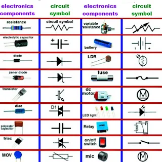
Electronic component symbols chart
Resistors (R)
The resistor is one of the simplest and most frequently used electronic components. Its primary function is to resist the flow of electric current. In circuit diagrams, a resistor is represented by a zigzag line, often accompanied by a value in ohms (Ω). The symbol for a resistor is "R," followed by a number indicating its resistance value. For example, "R1" might represent a 1-ohm resistor.
Capacitors (C)
Capacitors store and release electrical energy, and they are a crucial part of electronic circuits. The symbol for a capacitor resembles two parallel lines, with a gap between them, and it is represented by the letter "C" followed by a value in microfarads (µF) or picofarads (pF). For instance, "C10µF" represents a capacitor with a capacitance of 10 microfarads.
Inductors (L)
Inductors, also known as coils or chokes, store energy in the form of a magnetic field. In circuit diagrams, the symbol for an inductor looks like a series of loops or coils and is represented by the letter "L." Inductance is typically measured in henrys (H), so you may see values like "L100mH" for a 100 millihenry inductor.
Diodes (D)
Diodes are semiconductor devices that allow current to flow in one direction only, acting as a one-way valve for electrical current. The symbol for a diode resembles an arrow, indicating the direction of current flow. The cathode (negative side) is marked with a line or triangle, and the anode (positive side) is left without a mark. For example, you might see "D1" on a circuit diagram, representing a diode.
Transistors (Q)
Transistors are the building blocks of modern electronics, serving as amplifiers, switches, and signal modulators. They come in various types, including bipolar junction transistors (BJTs) and field-effect transistors (FETs). In circuit symbols, transistors are represented by the letter "Q" followed by a unique identifier, such as "Q1" for the first transistor in the circuit.
Integrated Circuits (IC)
Integrated circuits, or ICs, are complex semiconductor devices that contain multiple electronic components on a single chip. These components can range from microprocessors to amplifiers to digital logic gates. ICs are often represented by a rectangular shape with pins extending from the sides. The specific function of the IC is typically labeled within the rectangle, such as "IC555" for a 555 timer IC.
Conclusion
Understanding electronic component circuit symbols is essential for anyone working with electronics. These symbols provide a concise and standardized way to represent components and their connections in circuit diagrams, making it easier to design, troubleshoot, and communicate about electronic circuits. Whether you're a seasoned engineer or a beginner in electronics, mastering these symbols is a critical step toward becoming proficient in the world of electronics. So, next time you encounter a circuit diagram, remember that these symbols are the key to unlocking the mysteries of electronic circuits.


No comments:
Post a Comment