google-site-verification: google6dca6ba7f9bb39a6.html electro point

BC108 transistor Datasheet Pinout and Applications

 BC108 Transistor Datasheet, Pinout, and Applications


Transistors are fundamental electronic components that play a crucial role in modern electronic devices and circuits. Among the many types of transistors available, the BC108 is a commonly used NPN bipolar junction transistor (BJT) known for its versatility and reliability. In this blog post, we will delve into the BC108 transistor, exploring its datasheet, pinout, and various applications.


Understanding the BC108 Transistor


The BC108 is a small-signal NPN transistor primarily designed for low to medium power amplification and switching applications. It is part of the BC1xx series of transistors, which includes the BC107 and BC109, each with slight variations in electrical characteristics. The BC108 transistor is widely available and reasonably priced, making it a popular choice for hobbyists and professionals alike.


 BC108 Transistor Datasheet


Before diving into its applications, let's take a look at the key specifications of the BC108 transistor as outlined in its datasheet:


**1. Electrical Characteristics:**


- **Collector-Base Voltage (V<sub>CB</sub>):** 30V

- **Collector-Emitter Voltage (V<sub>CE</sub>):** 25V

- **Emitter-Base Voltage (V<sub>EB</sub>):** 5V

- **Collector Current (I<sub>C</sub>):** 100mA

- **Power Dissipation (P<sub>TOT</sub>):** 250mW

- **DC Current Gain (h<sub>FE</sub>):** 100 - 630 (varies with collector current)

- **Transition Frequency (f<sub>T</sub>):** 150MHz


**2. Pin Configuration (Pinout):**


The BC108 transistor has three leads or pins, each with its unique function:


- **Collector (C):** This is the power supply pin for the transistor and is typically connected to the positive supply voltage in most applications.

- **Base (B):** The base pin controls the transistor's switching or amplification action. A small current applied to the base terminal can control a much larger current between the collector and emitter.

- **Emitter (E):** The emitter is the output pin. It allows the current to flow from the collector to the emitter when the transistor is in the "on" state.


 BC108 Transistor Pinout


Here is a graphical representation of the BC108 transistor pinout 


 Applications of BC108 Transistor


The BC108 transistor finds applications in various electronic circuits, thanks to its small size, low cost, and reasonable performance characteristics. Here are some common uses of the BC108 transistor:


### 1. Signal Amplification


One of the primary applications of the BC108 transistor is in signal amplification. By configuring it in a common-emitter amplifier circuit, you can increase the strength of weak electrical signals. This is useful in audio amplifiers, radio receivers, and various sensor interfaces.


### 2. Switching Applications


The BC108 can also be used as a switch in digital logic circuits. When used in a saturated mode, it allows a relatively large current to pass through the collector-emitter path, making it suitable for applications like turning on and off small motors, relays, or LEDs.


### 3. Oscillator Circuits


The BC108's high transition frequency makes it suitable for use in RF (radio frequency) oscillator circuits. It can generate high-frequency oscillations required for various radio communication applications.


### 4. Pulse Shaping


In pulse shaping circuits, the BC108 transistor can be used to shape or condition input pulses. This is useful in applications like pulse-width modulation (PWM) and signal waveform manipulation.


### 5. Voltage Regulation


By employing the BC108 in a voltage regulator circuit, you can maintain a stable output voltage despite variations in the input voltage or load. This is crucial in power supply applications.


## Conclusion


The BC108 transistor, with its compact size and versatile characteristics, is an essential component in the world of electronics. Whether you're amplifying signals, switching loads, or generating high-frequency oscillations, the BC108 can serve as a reliable building block for a wide range of electronic circuits. Understanding its datasheet and pinout is the first step toward harnessing its potential in your projects. As technology continues to advance, transistors like the BC108 remain indispensable tools for electronic engineers, hobbyists, and enthusiasts.

BC639 transistor datasheet pinout

BC639 Transistor Datasheet Pinout and Applications


Transistors are fundamental components in electronics, serving as switches or amplifiers for various applications. Among the countless transistor models available, the BC639 is a versatile NPN bipolar junction transistor (BJT) commonly used in a wide range of electronic circuits. In this blog post, we'll explore the BC639 transistor, its datasheet, pinout, and some of its applications.


Understanding the BC639 Transistor


The BC639 is part of the BC6xx series of transistors, which are known for their general-purpose usage. These transistors are designed for low-power applications and are often utilized in amplification and switching circuits. The BC639, in particular, features an NPN configuration, making it suitable for a variety of signal processing tasks.


BC639 Transistor Datasheet


Before delving into the pinout and applications, it's essential to familiarize yourself with the key specifications of the BC639 transistor, which can be found in its datasheet. Here are some of the crucial parameters:


1. Collector-Base Voltage (V<sub>CB</sub>): 

This specifies the maximum voltage that can be applied between the collector and the base terminals without causing breakdown. Typically, it is rated at 80V for the BC639.


2. Collector-Emitter Voltage (V<sub>CE</sub>): 

This parameter defines the maximum voltage that can exist between the collector and emitter terminals while the transistor is in the "on" state. The BC639 typically has a V<sub>CE</sub> rating of 80V.


3. Collector Current (I<sub>C</sub>): The maximum allowable current flowing from the collector to the emitter without causing damage to the transistor. For the BC639, this is typically rated at 1A.


4. HFE (Beta): The current gain or amplification factor of the transistor. It typically ranges between 40 and 160 for the BC639, depending on the specific model.


5. Power Dissipation (P<sub>TOT</sub>): This is the maximum amount of power the transistor can dissipate as heat without overheating. It is generally around 1.25W for the BC639.


6. Package Type: The BC639 transistor is available in various packages, including TO-92 and SOT-23, which determine its physical dimensions and mounting style.


BC639 Transistor Pinout


Now, let's take a closer look at the pinout of the BC639 transistor. Understanding the pinout is essential for proper circuit connection. The BC639 has three terminals:


1. Collector (C): This is the power input terminal. Current flows from the collector to the emitter when the transistor is in the "on" state.


2. Base (B): The base terminal is used to control the flow of current between the collector and emitter. A small current applied to the base can control a much larger current between the collector and emitter.


3. Emitter (E): The emitter terminal is the output terminal for the current flowing through the transistor. It allows the current to flow from the transistor to the external circuit.


Here is a simplified representation of the BC639 transistor's pinout:

<img src='bc639-transistor.gif' alt='Transistor BC639 Pinout'></img>


```

   C

   |

   E

   |

   B

```


It's crucial to connect the transistor correctly in your circuit to ensure it functions as intended.


 Applications of BC639 Transistor


The BC639 transistor's versatility makes it a valuable component in a wide range of applications, including:


1. Amplification: The transistor's ability to amplify small input signals makes it suitable for audio amplifiers, signal conditioning circuits, and sensor interfacing.


2. Switching: BC639 transistors are commonly used as switches in digital logic circuits, LED drivers, and relay drivers. They can control higher-power devices with a lower-power control signal.


3. Oscillators: When used in combination with other components, BC639 transistors can be part of simple oscillator circuits for generating various waveforms.


4. Voltage Regulation: In voltage regulation circuits, these transistors can be used to control the output voltage by adjusting the load current.


5. Signal Modulation: BC639 transistors are employed in amplitude modulation (AM) and frequency modulation (FM) circuits for radio broadcasting.


In summary, the BC639 transistor is a versatile and widely used component in electronic circuits due to its reliability, low cost, and ease of use. Its datasheet provides essential information for incorporating it into your projects, and understanding its pinout is crucial for proper circuit connections. Whether you're building amplifiers, switching circuits, or voltage regulators, the BC639 can be a valuable tool in your electronics toolkit.

9v dc transformerless power supply circuit diagram

 9V DC Transformerless Power Supply Circuit diagram 


Introduction


Power supplies are essential components in the world of electronics, providing a stable source of energy to run our devices. In many cases, we require a compact and cost-effective power supply that can deliver a specific voltage, such as 9V DC. One popular solution is a transformerless power supply circuit, which eliminates the need for a bulky and expensive transformer. In this blog post, we'll explore a simple yet efficient 9V DC transformerless power supply circuit diagram that you can easily build for your electronics projects.


Why Use a Transformerless Power Supply?


Transformerless power supplies are becoming increasingly popular for several reasons

1. Cost-Effective: Transformerless designs require fewer components compared to traditional transformer-based power supplies, making them more cost-effective.


2. Compact Size: They are significantly smaller and lighter, making them ideal for applications where space is limited.


3. Efficiency: Transformerless supplies can be highly efficient if designed correctly.


4. Reduced Heat Dissipation: With fewer components, there is less heat generated during operation.


5. Lower Weight: This is especially important for portable and battery-operated devices.


Let's dive into the circuit diagram and see how to build a 9V DC transformerless power supply.


Components You'll Need:


1. AC Voltage Source: Typically, this is your mains power supply (110V or 220V AC, depending on your region).


2. Diode Bridge (1N4007): Converts AC to pulsating DC.


3. Filter Capacitor (100uF, 25V): Smooths the pulsating DC to reduce ripple.


4. Voltage Dropping Capacitor (0.1uF, 250V): Provides further filtration and voltage division.


5. Zener Diode (9V, 1W): Regulates the voltage to 9V DC.


6. Resistor (10k ohms): Limits the current through the Zener diode.


7. LED (Optional): Indicates when the power supply is active.


Circuit Diagram:

<img src='circuit-diagram.gif' alt='9v Dc Transformerless Power Supply Circuit Diagram'></img>


Building the Circuit:


1. Safety First: Ensure you are well-versed in working with mains voltage. Always disconnect the power source when working on the circuit.


2. Diode Bridge: Connect the AC voltage source to the diode bridge, ensuring correct polarity.


3. Filter Capacitor: Connect the positive and negative terminals of the diode bridge to the filter capacitor.


4. Voltage Dropping Capacitor: Connect the positive terminal of the filter capacitor to the anode (positive) of the Zener diode. Connect the cathode (negative) of the Zener diode to the ground (negative) side of the filter capacitor.


5. Resistor and LED: If using an LED for indication, connect it in parallel with a resistor between the cathode of the Zener diode and ground.


6. Output: The output of the circuit is taken from the anode of the Zener diode and the ground. This will give you a stable 9V DC output.


Testing:


After assembling the circuit, carefully apply power to it. Measure the output voltage to ensure it is close to 9V DC. The LED, if used, should light up, indicating the power supply is active.


Conclusion:


A 9V DC transformerless power supply can be a convenient solution for various electronics projects where space and cost constraints are essential considerations. However, it's crucial to exercise caution when working with mains voltage and ensure your circuit is correctly assembled to provide a stable and safe power source for your devices. With the right components and proper assembly, you can create a reliable 9V DC power supply for your electronics projects.

BC337 transistor Datasheet pinout

 BC337 Transistor Datasheet and Pinout: 


Introduction


The BC337 transistor is a commonly used bipolar junction transistor (BJT) known for its versatility and widespread application in electronic circuits. Whether you're a beginner in electronics or an experienced hobbyist, understanding the BC337 transistor datasheet and pinout is essential for utilizing this component effectively. In this blog post, we'll delve into the datasheet and pinout of the BC337 transistor, helping you grasp its fundamentals and applications.


**BC337 Transistor Overview**


The BC337 is an NPN bipolar transistor that falls under the category of small signal transistors. These transistors are designed to amplify and switch small electronic signals. The BC337 transistor is part of the BC3xx series, with each variant having slightly different electrical characteristics. Here's a breakdown of the key specifications:


- Collector-Base Voltage (V_CB): Typically around 50V.

- Collector-Emitter Voltage (V_CE): Usually around 45V.

- Collector Current (I_C): Ranges from a few milliamperes to a few hundred milliamperes (mA).

- DC Current Gain (hFE): Varies with different BC337 types but typically ranges from 100 to 800.

- Maximum Power Dissipation (P_D): Typically around 625mW.


BC337 Transistor Pinout


Understanding the pinout of the BC337 transistor is crucial for proper integration into your electronic circuits. The BC337 transistor has three pins or terminals: the collector (C), the base (B), and the emitter (E). Here's a brief description of each:


1. Collector (C): This is the power supply terminal. The collector current flows from the collector to the emitter. In circuit diagrams, it's often represented as 'C' or 'C'.


2. Base (B): The base terminal controls the flow of current between the collector and emitter. It acts as a switch that allows or disallows current flow. In circuit diagrams, it's usually denoted as 'B' or 'B'.


3. Emitter (E): The emitter terminal allows the current to exit the transistor. In circuit diagrams, it's typically marked as 'E' or 'E'.


BC337 Transistor Datasheet


A datasheet is an essential document that provides detailed information about an electronic component, including its electrical characteristics, pinout, and usage guidelines. When working with the BC337 transistor, referring to its datasheet is highly recommended. Here are some key sections you'll find in a typical BC337 transistor datasheet:


1. **Electrical Characteristics**: This section lists the transistor's key electrical parameters, including voltage ratings, current ratings, and gain values.


2. **Absolute Maximum Ratings**: These are the maximum values for voltage, current, and power that the transistor can handle without risking damage.


3. **Pinout and Package Information**: A diagram showing the pinout of the transistor and information about its physical package.


4. **Recommended Operating Conditions**: This section suggests operating conditions such as voltage and current levels for optimal performance.


5. **Typical Application Circuit**: Often, a datasheet includes a sample circuit diagram illustrating how to use the transistor in a basic application.


6. **HFE vs. IC Characteristics**: A graph or table depicting the relationship between the collector current (IC) and the DC current gain (hFE) under various conditions.


7. **Package Dimensions**: Dimensions and mechanical specifications for the transistor's package.


Conclusion


Understanding the BC337 transistor datasheet and pinout is a valuable skill for anyone working with electronic circuits. It allows you to make informed decisions about component selection, usage, and integration into your projects. Whether you're amplifying signals, switching loads, or performing other tasks in your circuits, the BC337 transistor can be a reliable and versatile choice when used according to its datasheet specifications. Always refer to the datasheet for the specific BC337 variant you're using to ensure accurate information and optimal performance in your electronic designs.

Resistor

 Understanding Resistors

The Unsung Heroes of Electronics


Introduction


In the world of electronics, there are many components that play vital roles in shaping the behavior of circuits. One such unsung hero is the resistor. While it may seem like a simple and unassuming device, resistors are essential for controlling current, voltage, and ensuring the proper functioning of countless electronic devices. In this blog post, we'll delve into the world of resistors, exploring what they are, how they work, and why they are so crucial in the world of electronics.


What Is a Resistor?


A resistor is a passive two-terminal electronic component that opposes the flow of electric current. It is designed to have a specific electrical resistance, which is measured in ohms (Ω). Resistors are usually small, cylindrical components with color-coded bands that indicate their resistance value.

<img src='resistor.jpg' alt='Resistor'></img>


How Do Resistors Work?


At its core, a resistor's function is straightforward: it resists the flow of electrical current passing through it. This resistance is created by the resistor's material and physical properties. The most common type of resistor is the carbon composition resistor, which is made by mixing carbon granules with a binder material. Other types of resistors, such as metal film and wirewound, utilize different materials and construction methods to achieve their resistance properties.


When voltage is applied across the two terminals of a resistor, it generates a flow of current according to Ohm's law: V = I * R, where V represents voltage, I represents current, and R represents resistance. In simpler terms, the resistor limits the amount of current that can flow through it based on its resistance value.


Applications of Resistors


Resistors have a wide range of applications in electronics and play a fundamental role in circuit design. Here are some common applications:


1. Voltage Division: Resistors are used in voltage divider circuits to create specific voltage levels. This is useful for tasks like setting the brightness of an LED or dividing a voltage signal for measurement.


2. Current Limiting: In various electronic circuits, especially those involving LEDs, resistors are used to limit the current flowing through a component to prevent damage.


3. Signal Conditioning: Resistors are often used to shape and filter analog signals, making them suitable for further processing.


4. Temperature Sensing: Thermistors, a type of resistor with resistance that changes with temperature, are used in temperature measurement applications.


5. Pull-Up and Pull-Down Resistors: These are essential in digital circuits to ensure that input pins remain at known voltage levels when not actively driven by a signal.


Conclusion


In the world of electronics, resistors may not always steal the spotlight, but they are undoubtedly one of the unsung heroes that enable the functionality of countless devices we use every day. Whether it's controlling the brightness of your smartphone's screen, ensuring your car's engine runs smoothly, or allowing your computer to perform complex calculations, resistors are quietly doing their job to make it all possible.


As you continue your journey in the world of electronics, remember to appreciate the role of resistors in every circuit. They may seem simple, but their ability to control current and voltage is a fundamental building block of modern technology. So, next time you encounter a resistor, take a moment to acknowledge the crucial role it plays in powering the electronic world around us.

Electronic component symbols

 Demystifying Electronic Component Circuit Symbols


Introduction


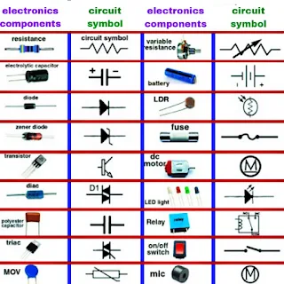
When it comes to understanding and working with electronic circuits, one of the fundamental aspects you need to grasp is the use of circuit symbols. These symbols serve as a universal language for engineers, technicians, and hobbyists alike to communicate and design electronic circuits effectively. In this blog post, we will explore the most common electronic component circuit symbols, shedding light on their meanings and applications.

Electronic component symbols chart 

<img src='electronic-component-symbols.jpg' alt='Electronic Component Symbols Chart></img>


Resistors (R)


The resistor is one of the simplest and most frequently used electronic components. Its primary function is to resist the flow of electric current. In circuit diagrams, a resistor is represented by a zigzag line, often accompanied by a value in ohms (Ω). The symbol for a resistor is "R," followed by a number indicating its resistance value. For example, "R1" might represent a 1-ohm resistor.


Capacitors (C)


Capacitors store and release electrical energy, and they are a crucial part of electronic circuits. The symbol for a capacitor resembles two parallel lines, with a gap between them, and it is represented by the letter "C" followed by a value in microfarads (µF) or picofarads (pF). For instance, "C10µF" represents a capacitor with a capacitance of 10 microfarads.


Inductors (L)


Inductors, also known as coils or chokes, store energy in the form of a magnetic field. In circuit diagrams, the symbol for an inductor looks like a series of loops or coils and is represented by the letter "L." Inductance is typically measured in henrys (H), so you may see values like "L100mH" for a 100 millihenry inductor.


Diodes (D)


Diodes are semiconductor devices that allow current to flow in one direction only, acting as a one-way valve for electrical current. The symbol for a diode resembles an arrow, indicating the direction of current flow. The cathode (negative side) is marked with a line or triangle, and the anode (positive side) is left without a mark. For example, you might see "D1" on a circuit diagram, representing a diode.


Transistors (Q)


Transistors are the building blocks of modern electronics, serving as amplifiers, switches, and signal modulators. They come in various types, including bipolar junction transistors (BJTs) and field-effect transistors (FETs). In circuit symbols, transistors are represented by the letter "Q" followed by a unique identifier, such as "Q1" for the first transistor in the circuit.


Integrated Circuits (IC)


Integrated circuits, or ICs, are complex semiconductor devices that contain multiple electronic components on a single chip. These components can range from microprocessors to amplifiers to digital logic gates. ICs are often represented by a rectangular shape with pins extending from the sides. The specific function of the IC is typically labeled within the rectangle, such as "IC555" for a 555 timer IC.


Conclusion


Understanding electronic component circuit symbols is essential for anyone working with electronics. These symbols provide a concise and standardized way to represent components and their connections in circuit diagrams, making it easier to design, troubleshoot, and communicate about electronic circuits. Whether you're a seasoned engineer or a beginner in electronics, mastering these symbols is a critical step toward becoming proficient in the world of electronics. So, next time you encounter a circuit diagram, remember that these symbols are the key to unlocking the mysteries of electronic circuits.

What is electricity

 What is Electricity: 

Unveiling the Mysteries of the Invisible Power


Introduction


Electricity is a fundamental force of nature that powers our modern world. It's an essential part of our daily lives, from lighting up our homes to running our smartphones and powering the machines that drive our industries. Despite its omnipresence, many people have only a basic understanding of what electricity is and how it works. In this blog post, we'll delve into the world of electricity to demystify its nature, origins, and its crucial role in our modern existence.

<img src='what-is-electricity.jpg' alt='two electric pole with wire line'/>


Understanding the Basics


Electricity is the result of the movement of electrons, subatomic particles that carry a negative electric charge. Atoms, the building blocks of matter, consist of protons, neutrons, and electrons. Electrons are the "free" particles that can move within certain materials, like metals and conductors, creating an electric current when they do so.


Electrostatic Force


Electricity begins with the concept of electrostatic force, which is the attraction or repulsion between electrically charged particles. When objects gain or lose electrons, they become charged. If an object loses electrons, it becomes positively charged, and if it gains electrons, it becomes negatively charged. Opposite charges attract, while like charges repel.


Electric Circuits


To harness electricity for practical purposes, we use electric circuits. An electric circuit is a closed loop or pathway through which electrons can flow. It consists of various components, including a source of electrical energy (such as a battery or generator), conductors (like wires), and devices (such as light bulbs or motors). When a circuit is complete, electrons can move from the negative terminal of the energy source, through the conductors and devices, and back to the positive terminal, creating a continuous flow of electricity.


Voltage, Current, and Resistance


Three key parameters help us understand and quantify electricity:


1. Voltage (V): Voltage is the electrical "push" or potential difference that drives electrons through a circuit. It's measured in volts (V) and provides the force needed to make electrons move. Think of it like water pressure in a hose - higher voltage means more force pushing the electrons.


2. Current (I): Current is the rate of flow of electric charge, typically measured in amperes (A or amps). It describes how many electrons pass through a point in a circuit per unit of time. It's like the flow rate of water in a hose.


3. Resistance (R): Resistance is the opposition to the flow of electrons in a material or component. It's measured in ohms (Ω). Think of resistance as a constriction in the hose that reduces the flow of water. Similarly, in a circuit, resistance restricts the flow of electrons.


Ohm's Law


Ohm's Law, formulated by the German physicist Georg Simon Ohm, relates voltage (V), current (I), and resistance (R) in a circuit through a simple equation: V = I × R. This law is a fundamental principle in understanding and working with electricity.


Conclusion


Electricity is a remarkable and indispensable force in our lives, making the world as we know it possible. From the tiniest microchip in your smartphone to the massive power grids that light up cities, the principles of electricity play a crucial role. Understanding the basics of voltage, current, resistance, and circuits allows us to harness this invisible power to improve our lives and advance technology. So, the next time you flip a switch or charge your devices, you'll have a better appreciation for the wonders of electricity that make it all possible.

5 band resistor color code chart


<img src='5-band-resistor-color-code-chart.jpg' alt='5 Band Resistor Color Code Chart'></img>


Introduction


In the world of electronics, resistors are like the unsung heroes. They play a crucial role in controlling the flow of current within a circuit, ensuring that electronic devices function as intended. To work with resistors effectively, one must understand how to read their color code chart. In this blog post, we'll delve into the 5-band resistor color code chart, a tool that allows engineers, hobbyists, and enthusiasts to identify a resistor's value quickly and accurately.


1. The Basics of Resistor Color Coding


Resistors are tiny components with various resistance values, which are measured in ohms (Ω). To make it easier to identify their resistance values, resistors are color-coded using a series of colored bands. The 5-band resistor color code chart provides a simple and standardized way to determine a resistor's resistance value, tolerance, and sometimes even its temperature coefficient.


2. Band Interpretation


The 5-band resistor color code consists of five colored bands, each representing a specific value or characteristic of the resistor:


   a. The First Band: This band represents the first digit of the resistor's value. Each color corresponds to a number (0-9), allowing you to determine the initial digit of the resistance.


   b. The Second Band: Similar to the first band, this one represents the second digit of the resistance value.


   c. The Third Band: The third band denotes the multiplier. It tells you how many zeros should be added after the first two digits to calculate the resistance value. For example, if the third band is red, the multiplier is 100.


   d. The Fourth Band (Tolerance Band): This band indicates the tolerance of the resistor, which tells you how much the actual resistance can deviate from the stated value. Common tolerance values include ±1%, ±2%, ±5%, and ±10%.


   e. The Fifth Band (Optional): Some resistors have a fifth band, which represents the temperature coefficient. It indicates how much the resistor's value changes with temperature variations.


3. Color Codes and Their Corresponding Values


To read the resistor color code, you need to know the color-to-number mapping. Here are the standard color codes and their corresponding values:


   - Black: 0

   - Brown: 1

   - Red: 2

   - Orange: 3

   - Yellow: 4

   - Green: 5

   - Blue: 6

   - Violet: 7

   - Gray: 8

   - White: 9


4. Example Calculation


Let's decipher a resistor's value using the 5-band color code as an example. Suppose you have a resistor with the following color bands: Yellow (4), Violet (7), Red (2), Gold (±5% tolerance). 

<img src='resistor.jpg' alt='Resistor 4.7k Ohm'></img>

- The first band (Yellow) represents the first digit, which is 4.

   - The second band (Violet) represents the second digit, which is 7.

   - The third band (Red) represents the multiplier, which is 100.

   - The fourth band (Gold) indicates the tolerance, which is ±5%.


Now, you can calculate the resistance value as follows:


Resistance Value = (47 * 100) Ω = 4,700 Ω or 4.7 kΩ with a tolerance of ±5%.


Conclusion


The 5-band resistor color code chart is an essential tool for anyone working with electronics. It simplifies the process of identifying a resistor's resistance value, tolerance, and sometimes its temperature coefficient. By mastering this color code, you can confidently work with resistors in your electronic projects and troubleshoot circuits effectively. So, the next time you encounter a mysterious resistor, remember that its color bands hold the key to its value and purpose in your circuit.

BC547 transistor pinout datasheet and applications

BC547 Transistor Pinout, Datasheet, and Applications Introduction Transistors are the building blocks of modern electronics, playing ...